Saturday, December 20, 2008

Dog Clutch Re-Visited


Dog Clutch Re-Visited

I have now made the new dog clutch, well twice actually as I made the same mistake as the first firm that made it did. The balls in the CV joint do not run in the bottom of the grooves in the CV joint but 10 thou off the bottom. So making it to that measurement made the first attempt 20 thou out. The last pic is with the Cavalier inner CV boot with an oil seal on the little end. When the clutch is dis-engaged the clutch and CV boot will rotate and the prop shaft will remain still.

Dog Clutch


Dog Clutch


The Dog clutch is the next thing to come under scrutiny. I first had this made for me be for I had my own lathe. I wanted it made of ali, but it came over engineered made of steel and heavy. Also when disengaged the CV inner was far too loose and would probably rattle. I have also changed my mind on the reverse and no longer need the "V" puly.

Taking the old dog clutch apart was difficult to say the least. It would not pull apart in the vice so I cut three slits in the sleeve that goes over the CV joint, still no joy. Next came the blow lamp and a bigger hammer, it would not budge. I machined the sleeve off completely, that left the remaining bit just butted up to the CV joint. I then noticed that I had used a small bead of stixall as a sealant when I assembled it. It still needed a large lump hammer to part it! As I said amazing stuff that Stixall.

Friday, December 19, 2008

Gearbox Output Pix


Gearbox Output

Now the shaft comes out of the back of the "gearbox" strait and true I now have to move the location hole for the Mini drive shaft bearing housing to locate. Tom & Jerry make moving a hole look easy but I had to cut a big hole in the casing and add a new bit with the hole in right place and captivate five nuts to hold the bearing housing.. By doing this I have made the rear casing a lot stronger as I have added 6mm to casing. The white stuff holding the nuts in the first pic is truly amazing stuff called Stixall

Machining Mini Bearing Housing


Straightening Clutch

After making the shaft true I had to put a needle roller thrust bearing on the end to hold the shaft in position to allow a small amount of end float. The first picture showes how I added a layer of harder alloy to the piece of aluminium that will become the bearing location. The next pic is it finished. And then located.

I had a hardened steel bearing washer that had to be fixed to the inside of the Mini drive shaft bearing housing. Before I could locate it I had to machine the housing. Holding the housing in the lathe chuck was a challenge.

Reworking Clutch Pix


Reworking Clutch


I have been very busy making small progress. My converter to dog-clutch shaft was a little out of true, I thought I would straighten it up by puting it on the lathe heating it up evenly as it is turning and then tapping it until it is true. This did not work, once it got to the critical temperature for the Lumiweld (about 500 degrees C) it fell apart. I was not too surprised at this and it gave me the chance to re machine the face and set it up before re doing the Lumiweld. I made a sort of vertical spit roast device for the lathe so as I could rotate the shaft vertically as I heated it up evenly to re apply the Lumiweld. All went well, the shaft cooled down perfectly true. But cleaning up the welded bit I found a small empty pocket that may have effected the balance. So I re-heated it, flowed a bit more Lumiweld in as I taped it to get the air out. It looked perfect but it was out of true again. So re-heat take apart re machine, add a few few bolts an d now it is true again.

Friday, September 12, 2008

Tyre Dilemma

I have always planed to use 13" wheels on my Berkeley project car. My previous car had 13" wheels with 175/50VR13 tyres made by Yokohama. I had always resisted going too wide on my three wheelers on the assumption that the low car weight would not give enough lbs/in squared over the contact patch. I once used a low profile 185 on the back and found that although excellent in the dry and excellent handling up to 150mph but was a bit disappointing in the wet aquaplaning at a lower speed than previous tyres. But that was 14 years ago and tyre compounds have improved since then.

I have now learnt that the contact patch will be the same no mater how wide the tyre, the thing that changes is the contact patch shape and the size is dependant on tyre pressure.

My dilemma is that the new car will be capable of speeds well in excess of 150mph and that would require a rating of "Z", and to my knowledge that rating is not available in 13".

I may be worrying unduly here as the difference in compound between VR and ZR is only slight and the speed rating is based on the ability to withstand higher temperatures and as temperatures are weight related my lighter than normal car may be ok.

Monday, September 8, 2008

Bungee Graph

Graph Text

I took a load of measurements at approximately every half inch. I have made a graph to show the way the rate raises. I started with a bit of tension because of the way I set the test up. The best part of the graph is between 14" and 18". I used two 22" bungees and stretched them to 44".so the diagram starts when the chords are stretched to 26". I am going to try bicycle inner tube tomorrow with and without air.

Wednesday, September 3, 2008

Front Suspension Draft


Suspension Musings

Before I can finalize my suspension design I will need to know my CofG height, and that means I will have to have my roof, floor, space frame and roll bar in the equation. The rubber that I intend to use is this stuff http://www.ci-band.com/ . It is very thin and so I can make it up in multiple layers. I want a rising rate and my gut feeling is that I can leave the rate rise to the properties of the rubber, provided that the geometry of the suspension does not give me a falling rate like angled coil over’s do. I will give a rough sketch to show you my ideas

Power Vectoring


Rear Hub


Crown Wheel And Drive Shaft


Converter To Dog Clutch Shaft


Saturday, August 30, 2008

When I re conditioned the engine I thought I would make a few modifications. Power wise it was pretty much where I wanted it, but could not help making a few tweaks. For 90% of the time the engine will be operating at low engine speeds so I did not want to upset the high torque at low revs, the higher revs of the standard engine will be able to push the car to high enough speeds, 180mph at 5500rpm so the camshaft would remain the standard item. I gas flowed the head to improve low torque and economy and put a 390cfm 4 barrel Holly carb to improve response time and reduce engine height.
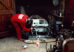
The first pic (reverse order) shows how I shortened the engine to get it in. I have an electronic controlled electric water pump mounted remotely to help shorten the engine, this will give better temperature control. When such a big engine is called upon to produce only small amounts of power at 60 or 70 mph it is likely to run too cold due to high air flow and large surface area of the engine, but in traffic or after driving hard and coming to a standstill, the confines of the Berkeley engine bay may lead to overheating.
The alternator is from a Suzuki Swift and is re-positioned to be driven by the power steering pulley attached to the crank damper further shortening the engine and making it lighter.
I made a new lower sump from aluminum to reduce weight (next pic).
Using the torque converter as the gearbox was the key to getting the engine in the Berkeley. Taking the drive from the drive plate at the back of the transmission pump was the main problem here. I did it by encapsulating the drive plate in molten metal and a small Mini differential output shaft (next 3 pics) that connects the drive to my dog clutch made from a Mini CV joint.

Wheel Hubs and Calipers

Space Frame to Sill Fixing

Space Frame 4

Space Frame 1

Rear Wishbones

Prop Shaft

Plan View V8 Berkeley

Phosphor Bronze Thrust Bearing

Pace Frame 3

Hub Test 3

Hub Test 2

Hub Test 1

Housing For Plate Wheel Hub

High Tensile Bolt Testing

Gear Box Mod Bonding

Gear Box Mod 739

Gear Box Casing Rear

Gear Box Case Looking At Drive

Fitting Plate To Wheel Hub

Final Drive Hub Thrust Plate

Final Drive Hub

Drive Train Position C

Drive Train Position B

Drive Train Position A